Welcome to Verilog Beginner's Tutorial! In this first post of the tutorial series, I will explain how to write an efficient Verilog code to ensure a stable design. It is assumed that the reader knows the basic terms in Verilog, here I will be dealing with how and when to use them.
Any Verilog code has a flow as follows:
1. Inputs and outputs declaration
2. Registers and Wires declaration
3. Verilog Logic Code
Sequential Part:

next_seq is a combinational variable and gets its value from a combinational block.

Then next_seq will directly take this input.

The advantage of this method is that combinational and sequential logic are kept in two separate blocks. This is a good coding practice and prevents confusion.
Basic Verilog code flow:
Note:
We use Blocking assignments (=) for combinational logic (executed step-by-step) and Non-Blocking assignments (<=) for sequential logic (all statements executed together).
Any Verilog code has a flow as follows:
1. Inputs and outputs declaration
2. Registers and Wires declaration
3. Verilog Logic Code
Verilog logic code can be split into 2 parts:
1. Combinational Part: This involves logic gates whose outputs change immediately on changing the inputs.
2. Sequential Part: This involves flip-flops whose outputs change only in response to a clock signal.
Combinational Part:
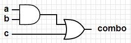
1. wire declaration is used here, when you have a fixed logical expression associated with the variable.
Variables declared as wire are used along with assign statements outside an always block.
Variables declared as wire are used along with assign statements outside an always block.
Eg. wire combo;
assign combo = (a & b) | c; //fixed logical expression
Logic for this:
 2. When we know some conditions on when to change the variable value, then we use always @ (input)
Note 1: always @ (input) block executes whenever there is an input change.
Note 2: variables on the LHS of an always block are always declared as reg.
Eg. always @ (b)
a = c & d;
This means a gets the logical AND of c and d only when input b changes (either 1 to 0 or 0 to 1).
To execute statements for any input change, use always @ (*) block.
Logic for this:
Note 1: always @ (input) block executes whenever there is an input change.
Note 2: variables on the LHS of an always block are always declared as reg.
Eg. always @ (b)
a = c & d;
This means a gets the logical AND of c and d only when input b changes (either 1 to 0 or 0 to 1).
To execute statements for any input change, use always @ (*) block.
This way we model Combinational Logic.
Sequential Part:
1. reg declaration is used here, to store data bits and used as the output of a flip-flop.
Sequential variables are initialized within an always block and are modelled as D flip-flops in hardware.
Here, seq is a sequential variable.
Eg. reg seq, next_seq;
always @ (posedge clk)
always @ (posedge clk)
begin
seq <= next_seq;
end
Input to the flip-flop 'seq' is usually given the name 'next_seq' as seq gets the value of next_seq after 1 clock pulse. (Naming convention can vary)
Input to the flip-flop 'seq' is usually given the name 'next_seq' as seq gets the value of next_seq after 1 clock pulse. (Naming convention can vary)

During every CLK pulse, seq gets the value of next_seq.
This way we model Sequential Logic.
next_seq is a combinational variable and gets its value from a combinational block.
The value taken by next_seq depends on the implementation.
If we are directly passing an input as shown

Then next_seq will directly take this input.
always @ (*)
begin
next_seq = input;
end
But if we have some combo logic before the flop, then next_seq will take the result of that combinational logic.

always @ (*)
begin
next_seq = //result of that combinational logic
end
Basic Verilog code flow:
module name (port1, port2);
input ip;   //Inputs
output op;  //Outputs

//Registers and Wires
reg ip_reg;
wire op_wire;

assign op_wire = 1'b0; //assign statements for wire logic

always @ (posedge clk)  //Sequential block
begin
         //all statements here are D flip-flops
end

always @ (*)  //Combinational block
begin
          //perform combinational operations
end
Note:
Now the above method of gate-level/data flow modelling is easy when we have obtained the logic diagram for a design and we know exactly our combinational and sequential elements.
Behavioral Code Analysis
A digital designer must always be able to deduce the logic circuit for any Verilog code.
The logic for Gate-Level or Dataflow modelling can be directly inferred.
Let us check this for Behavioral Modelling.
The most common constructs used here are if-else and case statements.
Case
A case statement selects one option from the many available options based on a selection variable.
This is exactly how a multiplexer works and so, a single multiplexer can be inferred in hardware.
Here we have a 4:1 multiplexer as there are 4 conditions.


This is how the logic will be realized using if-else and case constructs.
The process in which a Verilog code is converted to hardware logic is called synthesis.
Alright, now that the rules have been told, let's check out an example code in Verilog Tutorial 2.
Behavioral Code Analysis
A digital designer must always be able to deduce the logic circuit for any Verilog code.
The logic for Gate-Level or Dataflow modelling can be directly inferred.
Let us check this for Behavioral Modelling.
The most common constructs used here are if-else and case statements.
Case
A case statement selects one option from the many available options based on a selection variable.
case(sel)
2'b00: out = in_1;
2'b01: out = in_2;
2'b10: out = in_3;
2'b11: out = in_4;
This is exactly how a multiplexer works and so, a single multiplexer can be inferred in hardware.
Here we have a 4:1 multiplexer as there are 4 conditions.
If-else
An if-else statement checks various conditions based on priority.
if (sel[0])
out = in_3;
else if (sel[1])
out = in_2;
else
out = in_1;
This will result in a chain of multiplexers as shown. The mux closest to the output is due to the highest priority condition and then they are arranged backwards according to decreasing priority.
The process in which a Verilog code is converted to hardware logic is called synthesis.
Alright, now that the rules have been told, let's check out an example code in Verilog Tutorial 2.
No comments:
Post a Comment