Here is a practice question in Verilog where we implement a gated clock divider with the given specifications.
Gated Clock Divider in Verilog
Clock Gating: Clock gating is a low power design concept which helps to turn off the clock whenever not required. This helps to save power when the clock is not being used.
Requirement: Design a gated clock divider in Verilog (50% duty cycle) that can divide the clock frequency by any integral value. An enable signal indicates whether the clock divider is turned on or off.
Modules to be used:
clkdiv - top module for clock divider
down_counter - module to perform counting operations (down counter must be used)
Specifications:
Input signals for clkdiv:
inclk (input clock)
rst_n (active low reset)
enable (enable clock divider)
value (4 bits, clock divider value)
Output signals for clkdiv:
outclk (output clock after clock division)
Hints:
Let us now see how we can go about solving the problem.
For clock divider by an integer N, we have seen in an earlier post here:
Clock divider by even number
Only difference being instead of using an up counter to count from 0 to N/2, we now use a down counter to count from N/2 - 1 to 0.
That was quite easy to implement. Now for clock division by an odd integer N, we need a little more intuitive thinking and some mathematical skills!
This website explains it in detail.
Clock divider by odd number
Source: referencedesigner.com
So that was tricky! Our job now is to combine the above two modules and ensure that this clock divider works for any integer value of N.
Also to add is the enable signal. Only when enable is high, the clock divider must work.
Solution:
As mentioned earlier, the down counter module will perform our counting and required signals can be passed on to it. We will have a poscnt and a negcnt, since we need to count on the positive as well as negative clock edges (for clock divide by odd number).
The top module clkdiv will instantiate the counter. Since we have a different logic for odd and even values of clkdiv_val, we will need to select the correct logic based on the value.
- Signal outclk checks if we are out of reset and enable is high. If so, check whether value is an odd or even number and select outclk_odd or outclk_even respectively.
- outclk_even is computed in the sequential block.
- outclk_odd is computed using assign statement based on the logic to implement clock division by an odd number. If we have value=1, then the input clk is directly passed.
- Also see that we are not decrementing counter (poscnt and negcnt) when enable is turned off and counter value is zero. This helps save power by eliminating unnecessary toggling of bits.
Verilog Code:
module clkdiv (
	inclk,
	rst_n,
	enable,
	value,
	outclk
    );

input inclk;
input rst_n;
input enable;
input [3:0] value;
output outclk;

reg outclk_even;

wire [3:0] poscnt;
wire [3:0] negcnt;

wire outclk_odd;
wire outclk;

assign outclk_odd = (enable & value==1) ? inclk : (poscnt > (value>>1)) || (negcnt > (value>>1));
assign outclk = (!rst_n || !enable) ? 1'b0 : (!value[0]) ? outclk_even : outclk_odd;

always @ (posedge inclk or negedge rst_n)
begin
  if(!rst_n)
  begin
    outclk_even <= 1'b0;
  end
  else
  begin
    outclk_even <= (enable && (poscnt == 0)) ? ~outclk_even : outclk_even;
  end
end

down_counter u_down_counter (
	.clk     (inclk),
	.rst_n   (rst_n),
	.en      (enable),
	.div_val (value),
	.poscnt  (poscnt),
	.negcnt  (negcnt)
	);

endmodule

//4-bit down counter module
module down_counter(
	clk,
	rst_n,
	en,
	div_val,
	poscnt,
	negcnt
	);

input clk, rst_n;
input en;
input [3:0] div_val;

output [3:0]poscnt;
output [3:0]negcnt;

reg [3:0]poscnt, next_poscnt;
reg [3:0]negcnt, next_negcnt;

always @ (posedge clk or negedge rst_n)
begin
 if (!rst_n)
 begin
 poscnt <= 3'b0;
 end
 else
 begin
 poscnt <= next_poscnt;
 end
end

always @ (negedge clk or negedge rst_n)
begin
 if (!rst_n)
 begin
 negcnt <= 3'b0;
 end
 else
 begin
 negcnt <= next_negcnt;
 end
end

always @ (*)
begin
  if (en && poscnt==0)
  begin
    next_poscnt = !div_val[0] ? (div_val>>1) - 1 : div_val-1;
    next_negcnt = !div_val[0] ? 4'd0 : div_val-1;
  end
  else
  begin
    next_poscnt = (|poscnt) ? poscnt - 1'b1 : poscnt;
    next_negcnt = (|negcnt) ? negcnt - 1'b1 : negcnt;
  end
end

endmodule
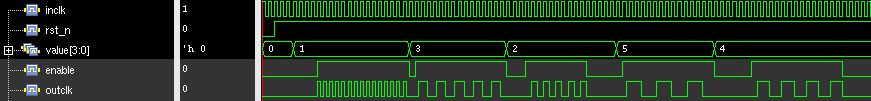
module clkdiv_tb;

// Inputs
reg inclk;
reg rst_n;
reg enable;
reg [3:0] value;

// Outputs
wire outclk;

// Instantiate the Unit Under Test (UUT)
clkdiv uut (
	.inclk(inclk),
	.rst_n(rst_n),
	.enable(enable),
	.value(value),
	.outclk(outclk)
);

  always #5 inclk = ~inclk;

initial begin
	// Initialize Inputs
	inclk = 1;
	rst_n = 0;
	enable = 1'b0;
	value = 0;
	#20 rst_n = 1'b1;
	enable = 0;
	value = 0;
	#30 value = 1;
	#40 enable = 1'b1;
	#150
	enable = 1'b0;
	value = 3;
	#10 enable = 1'b1;
	#150
	enable = 1'b0;
	value = 2;
	#30 enable = 1'b1;
	#100 enable = 1'b0;
	#50 value = 5;
	#10 enable = 1'b1;
	#150
	enable = 1'b0;
	value = 4;
	#60 enable = 1'b1;
	#150 enable = 1'b0;
	#50
	$finish;
end

endmodule
No comments:
Post a Comment